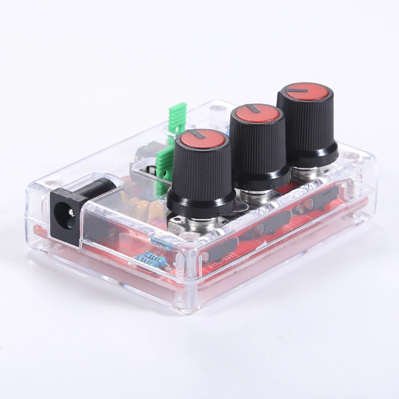
XR2206 Function Signal Generator DIY Kit Sine/Triangle/Square Output 1Hz-1MHz Signal Generator Adjustable Frequency Amplitude
XR2206 Function Signal Generator DIY Kit Sine/Triangle/Square Output 1Hz-1MHz Signal Generator Adjustable Frequency Amplitude
In stock
-
All orders are dispatched the next 3 business days!
-
We will beat any price. We back all products with a 1 year guarantee.
Order in the next 0 hours 0 minutes to get it by /06/2026
Couldn't load pickup availability
Guaranteed Safe Checkout
Description
Features:
1.High resolution, can generate sine/triangle/square waveforms.
2.Frequency range: 1Hz-1MHz.
3.Adjustable frequency and amplitude.
4.Frequency adjustment features coarse tuning and fine tuning.
5.Wide power supply range, use 9-12V external power or 9V battery(NOT Included).
Parameters:
-Voltage supply: 9-12v DC input
-Waveform: square wave, sine, and triangle
-Impedance: 600 ohms+10%
-Frequency: 1Hz -1 MHz
sine wave
-Amplitude: 0-3v, at 9v DC input
-Distortion: Less than 1% (11000 people)
-Flatness:+0.05db ± 1Hz -100 khz
square wave
-Amplitude: 8v (no-load), input at 9v DC
-Rise time: less than 50ns
-Descending time: less than 30ns
-Symmetry: less than 5%
Triangular wave
Amplitude: 0-3v, at 9v DC input
Linearity: less than 1% (up to 100 khz) 10ma
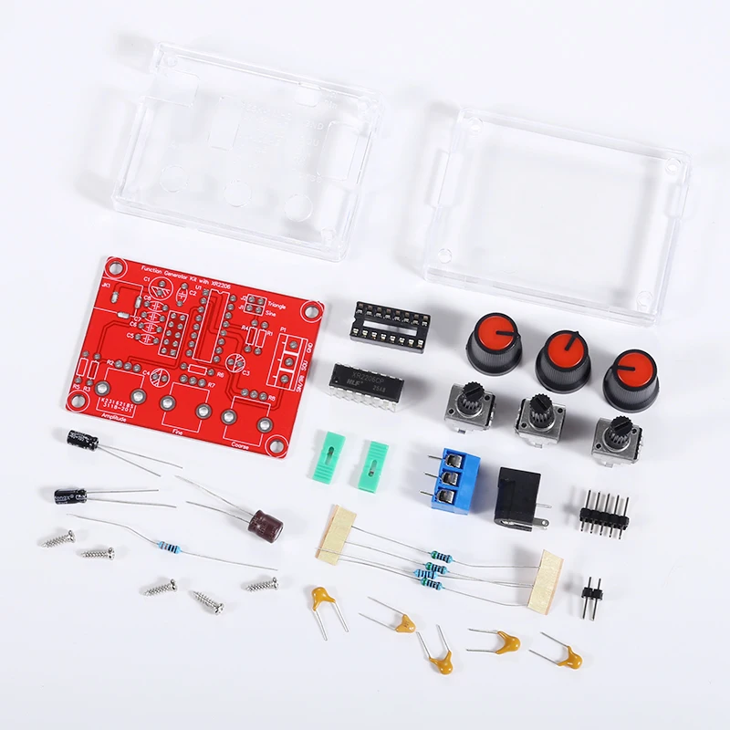
Package include:
1* DIY kit / finished product
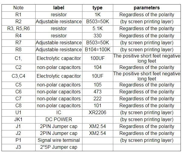
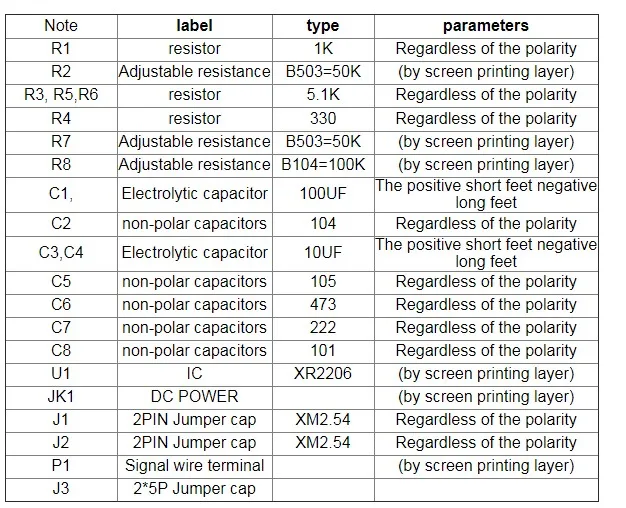
The Function Generator component parameter table
The welding installation considerations, follow these steps:
1. The components are welding the front board, from low to high principles, namely the first low welding components, such as, capacitor, resistor, diode, etc.
2.Welding IC socket, terminal blocks, finally power socket, adjustable potentiometer.
3.The back with a diagonal cutting pliers to cut short the pins as far as possible
Debugging steps:
1After completion of welding on IC, XR2206, pay attention to the direction of IC, insert the might damage the chip!
2. check the IC whether against, such as anti please timely correction.
3. Insert the power supply, power supply for 5.5 * 2.1 port, inside outside is negative polarity. For 9-12 v power supply voltage. The waveform may not be stable for more than 12 v
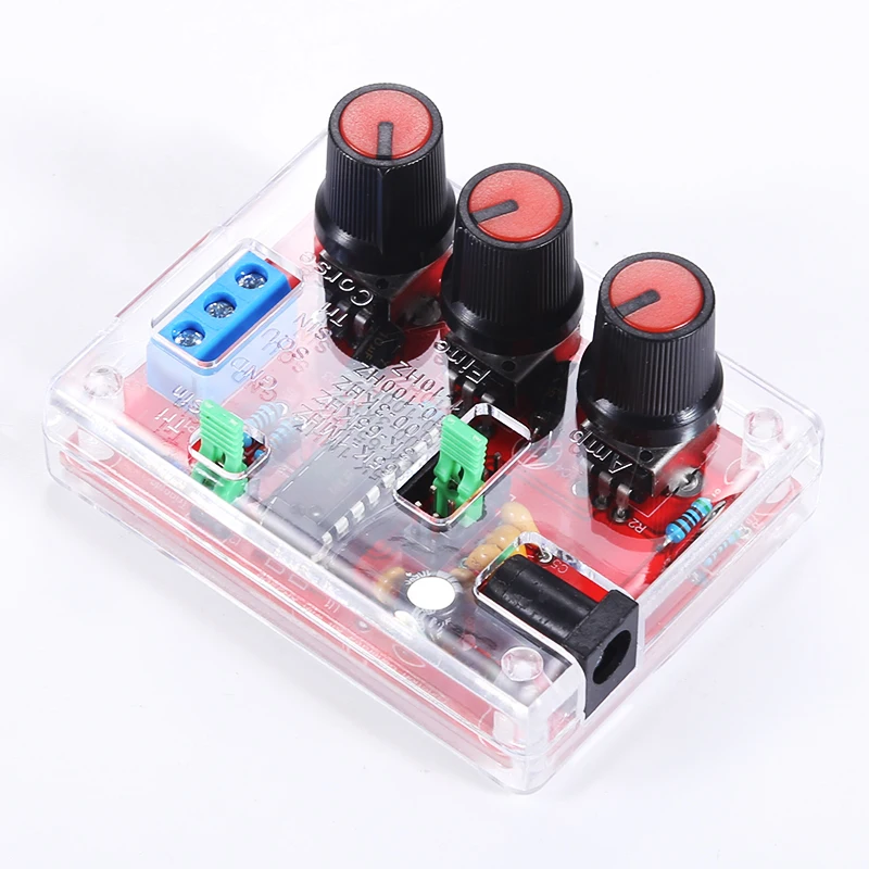
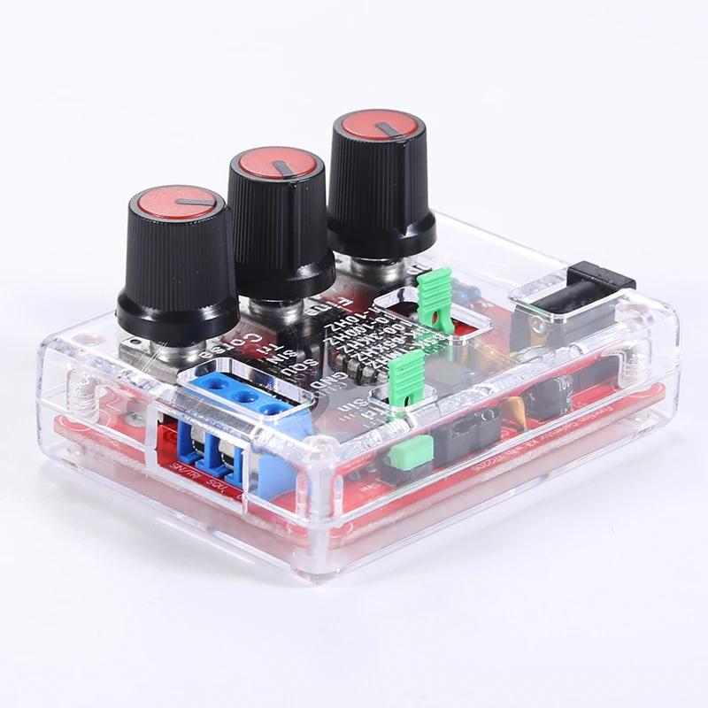
Using the step
1. J1 jumper cap plug in, SIN/TRI blue terminals output sine wave (note J1, J2 can only insert one of)
2. J2 jumper cap plug in, SIN/TRI blue terminals output triangular wave (note J1, J2 can only insert one of)
3. SQU blue terminals output pulse
4. AMP : Sine wave, triangle wave amplitude adjustment
5. FINE : Frequency fine adjustment
6. Coarse : Frequency of coarse adjustment
note:
If you buy DIY kits, need to solder yourself
Description
Description
Description
Features:
1.High resolution, can generate sine/triangle/square waveforms.
2.Frequency range: 1Hz-1MHz.
3.Adjustable frequency and amplitude.
4.Frequency adjustment features coarse tuning and fine tuning.
5.Wide power supply range, use 9-12V external power or 9V battery(NOT Included).
Parameters:
-Voltage supply: 9-12v DC input
-Waveform: square wave, sine, and triangle
-Impedance: 600 ohms+10%
-Frequency: 1Hz -1 MHz
sine wave
-Amplitude: 0-3v, at 9v DC input
-Distortion: Less than 1% (11000 people)
-Flatness:+0.05db ± 1Hz -100 khz
square wave
-Amplitude: 8v (no-load), input at 9v DC
-Rise time: less than 50ns
-Descending time: less than 30ns
-Symmetry: less than 5%
Triangular wave
Amplitude: 0-3v, at 9v DC input
Linearity: less than 1% (up to 100 khz) 10ma
Package include:
1* DIY kit / finished product
The Function Generator component parameter table
The welding installation considerations, follow these steps:
1. The components are welding the front board, from low to high principles, namely the first low welding components, such as, capacitor, resistor, diode, etc.
2.Welding IC socket, terminal blocks, finally power socket, adjustable potentiometer.
3.The back with a diagonal cutting pliers to cut short the pins as far as possible
Debugging steps:
1After completion of welding on IC, XR2206, pay attention to the direction of IC, insert the might damage the chip!
2. check the IC whether against, such as anti please timely correction.
3. Insert the power supply, power supply for 5.5 * 2.1 port, inside outside is negative polarity. For 9-12 v power supply voltage. The waveform may not be stable for more than 12 v
Using the step
1. J1 jumper cap plug in, SIN/TRI blue terminals output sine wave (note J1, J2 can only insert one of)
2. J2 jumper cap plug in, SIN/TRI blue terminals output triangular wave (note J1, J2 can only insert one of)
3. SQU blue terminals output pulse
4. AMP : Sine wave, triangle wave amplitude adjustment
5. FINE : Frequency fine adjustment
6. Coarse : Frequency of coarse adjustment
note:
If you buy DIY kits, need to solder yourself
Item Specifics
Item Specifics