VI Curve Tester Two-Channel Input (Acrylic Version Dual-Channel Display) Shows Four Test Frequencies
VI Curve Tester Two-Channel Input (Acrylic Version Dual-Channel Display) Shows Four Test Frequencies
In stock
-
All orders are dispatched the next 3 business days!
-
We will beat any price. We back all products with a 1 year guarantee.
Order in the next 0 hours 0 minutes to get it by /07/2026
Couldn't load pickup availability
Guaranteed Safe Checkout
VI Curve Tester Two-Channel Input (Acrylic Version Dual-Channel Display) Shows Four Test Frequencies
Features:
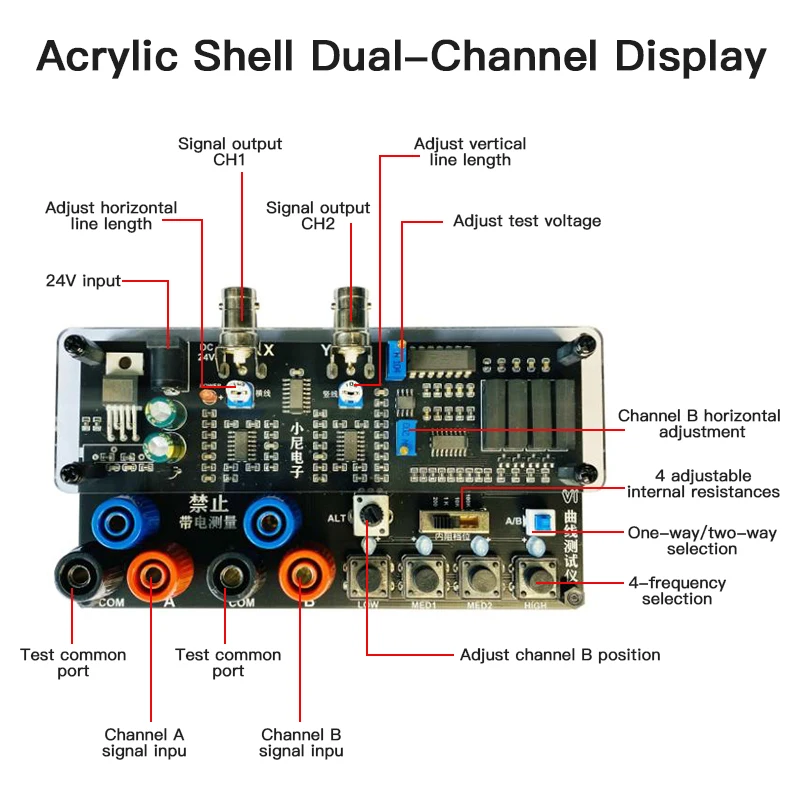
- Acrylic version with two-channel display
- Dual-channel signal input
- Two channels simultaneously display 4 frequencies
- 4 adjustable internal resistances
- One key to open dual-channel display
- Adjustable channel B position
Package Included:
- 1 x VI Curve Tester
- 1 x Set of Test Leads
- 1 x Connecting Cable
Oscilloscope Parameter Settings:
- Adjust your oscilloscope to X-Y mode (different oscilloscopes have different adjustment methods, please explore by yourself)
- The vertical parameters of X/Y 2 channels are adjusted to 1V/div, and a single trace oscilloscope only needs to adjust one.
- Analog oscilloscope does not need to adjust the time base; digital oscilloscope time base is adjusted to 1-5ms
- When connected correctly, the oscilloscope will display a horizontal line. If the vertical line is displayed, the XY plugs need to be reversed.
- The horizontal and vertical lines are in the display frame when adjusting the vertical and horizontal parameters.
Connect Analog Oscilloscope:
The connection of the analog oscilloscope is relatively simple. Different oscilloscopes are slightly different. Adjust an oscilloscope to the X-Y mode. Some oscilloscopes are selected by pressing buttons, and some are selected by the knob to the XY mode. Please research by yourself. Connect your oscilloscope with a BNC cable and then power on, a horizontal line will be displayed under normal conditions. Adjust the XY vertical channel parameters by about 1V/div, and then adjust the XY attenuation so that the horizontal line is in the display frame. The horizontal line length can also be adjusted via the X attenuation potentiometer on the VI tester board. Short-circuit the test leads, a vertical line will be displayed under normal conditions. If the vertical line is too long or too short, you need to adjust the Y channel parameters so that the vertical line is within the display frame, generally half a grid or 1 grid to the edge. When the horizontal and vertical lines are normal, you can enter the normal measurement.
Connect Digital Oscilloscope:
Enter the XY mode of your digital oscilloscope through the menu or keys, and adjust the two channels of X and Y to 1V/div. The single-trace oscilloscope only needs to adjust the Y channel. The adjustment time base is 1-5ms. Select DC coupling for X Y channels with 1X attenuation. When the oscilloscope is not connected, the screen should be a bright spot, adjust the horizontal and vertical so that the bright spot is centered. After the VI tester is connected, there is normally a horizontal line. Adjust the 103 potentiometer at the top of the VI board so that the horizontal line is within the display frame, half a grid or 1 grid to the edge. Short-circuit the test leads, the display should be a vertical line at this time, adjust the Y channel parameters so that the vertical line is in the display box. At this point, the debugging is over.
Test Online Circuit Board:
When testing a circuit board online, the circuit board should not be charged. If there is a large capacitor on the circuit board, discharge the capacitor first, otherwise the VI test board will be burnt out.
Description
Description
VI Curve Tester Two-Channel Input (Acrylic Version Dual-Channel Display) Shows Four Test Frequencies
Features:
- Acrylic version with two-channel display
- Dual-channel signal input
- Two channels simultaneously display 4 frequencies
- 4 adjustable internal resistances
- One key to open dual-channel display
- Adjustable channel B position
Package Included:
- 1 x VI Curve Tester
- 1 x Set of Test Leads
- 1 x Connecting Cable
Oscilloscope Parameter Settings:
- Adjust your oscilloscope to X-Y mode (different oscilloscopes have different adjustment methods, please explore by yourself)
- The vertical parameters of X/Y 2 channels are adjusted to 1V/div, and a single trace oscilloscope only needs to adjust one.
- Analog oscilloscope does not need to adjust the time base; digital oscilloscope time base is adjusted to 1-5ms
- When connected correctly, the oscilloscope will display a horizontal line. If the vertical line is displayed, the XY plugs need to be reversed.
- The horizontal and vertical lines are in the display frame when adjusting the vertical and horizontal parameters.
Connect Analog Oscilloscope:
The connection of the analog oscilloscope is relatively simple. Different oscilloscopes are slightly different. Adjust an oscilloscope to the X-Y mode. Some oscilloscopes are selected by pressing buttons, and some are selected by the knob to the XY mode. Please research by yourself. Connect your oscilloscope with a BNC cable and then power on, a horizontal line will be displayed under normal conditions. Adjust the XY vertical channel parameters by about 1V/div, and then adjust the XY attenuation so that the horizontal line is in the display frame. The horizontal line length can also be adjusted via the X attenuation potentiometer on the VI tester board. Short-circuit the test leads, a vertical line will be displayed under normal conditions. If the vertical line is too long or too short, you need to adjust the Y channel parameters so that the vertical line is within the display frame, generally half a grid or 1 grid to the edge. When the horizontal and vertical lines are normal, you can enter the normal measurement.
Connect Digital Oscilloscope:
Enter the XY mode of your digital oscilloscope through the menu or keys, and adjust the two channels of X and Y to 1V/div. The single-trace oscilloscope only needs to adjust the Y channel. The adjustment time base is 1-5ms. Select DC coupling for X Y channels with 1X attenuation. When the oscilloscope is not connected, the screen should be a bright spot, adjust the horizontal and vertical so that the bright spot is centered. After the VI tester is connected, there is normally a horizontal line. Adjust the 103 potentiometer at the top of the VI board so that the horizontal line is within the display frame, half a grid or 1 grid to the edge. Short-circuit the test leads, the display should be a vertical line at this time, adjust the Y channel parameters so that the vertical line is in the display box. At this point, the debugging is over.
Test Online Circuit Board:
When testing a circuit board online, the circuit board should not be charged. If there is a large capacitor on the circuit board, discharge the capacitor first, otherwise the VI test board will be burnt out.
Item Specifics
Item Specifics