QPS6005S 1.8inch LCD DC-DC Step-down Power Supply module 6-62V Input 60V 5A 300w Output Voltage Current power Time +PC software
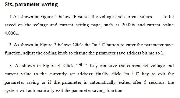
QPS6005S 1.8inch LCD DC-DC Step-down Power Supply module 6-62V Input 60V 5A 300w Output Voltage Current power Time +PC software
In stock
-
All orders are dispatched the next 3 business days!
-
We will beat any price. We back all products with a 1 year guarantee.
Order in the next 0 hours 0 minutes to get it by /06/2026
Couldn't load pickup availability
Guaranteed Safe Checkout

一、Instrument introduction
CNC step-down power supply is a fully NC programmable step-down power supply with small size, high power, high efficiency and stable work; it uses a 1.8-inch color LCD display to display comprehensive and clear data; the power supply is controlled by a 32-bit microprocessor It can accurately set and display the voltage and current; it uses buttons and knobs to operate in conjunction with convenient and fast setting parameters, and it can adjust the output voltage and current through the communication between the host computer and the computer and can monitor the output voltage and current in real time, which is very suitable for debugging and maintenance And experimental power.
二、Instrument characteristics
1.Using a 32-bit microprocessor, which can accurately set and display the output voltage and current;
2.Using 1.8-inch color LCD display, it can display the input voltage, output voltage, output current, power, capacity, time, temperature and power supply status in real time;
3.It is convenient and quick to adjust parameters through the combination of buttons and knobs, and the knobs have a button function, which can be adjusted by pressing the knobs, which is very convenient;
4.The output over-voltage protection (Ovp), over-current protection (Ocp), over-power protection (Opp), over-temperature protection (Otp), and input under-voltage protection (Lvp) can be set.When the output exceeds the set value, it can be set. Turn off output;
5.The resistance value of the (Res) power output connection line can be set, which can compensate the voltage drop on the wire;
6.The intelligent temperature-controlled cooling fan dissipates heat to ensure that the power device will not be damaged due to overheating;
7.Can output constant voltage and constant current;
8.With reverse input protection function, can prevent damage to the power supply due to reverse input;
9.With oscilloscope function, it can display the dynamically changing voltage and current curve;
10.Can realize secondary development by communicating with computer or other equipment through serial port;
Third, the technical indicators
|
project |
parameter |
|
Input voltage range |
6V~65V |
|
Output voltage adjustment range |
0 ~ 60v (input needs to be greater than output) |
|
Output current adjustment range |
0~5A |
|
Input protection method |
Reverse connection protection, (Lvp) under voltage protection |
|
Output protection mode |
(Ovp) over voltage, (Ocp) over current, (Opp) over power (Otp) over temperature protection |
|
Output Power |
0~300W |
|
Output voltage setting resolution |
10mV |
|
Output current setting resolution |
1mA |
|
Output ripple |
<100mVpp (input 48V, output 24V, current 5A) |
|
100Hz fluctuation transmission ratio |
< 1/10000 |
|
Typical efficiency |
92% (input 50v, output 30v, current 3a) |
|
Voltage and current display accuracy |
10mV、1mA |
|
Voltage display error |
±1%+10mV |
|
Current display error |
±2%+2mA |
|
Response time |
< 50ms |
|
Store operation |
m0 ~ m9 10 sets of parameter storage |
|
Cooling method |
Aluminum case cooling and cooling fan |
|
Cooling fan startup conditions |
Temperature value is greater than (otp-15) |
|
Operating ambient temperature |
0~60℃ |
|
Ambient storage temperature |
-20~70℃ |
|
Use environment |
Design for indoor use, maximum humidity 80% |
|
Dimensions (length x width x height) |
144×120×55(mm) |
|
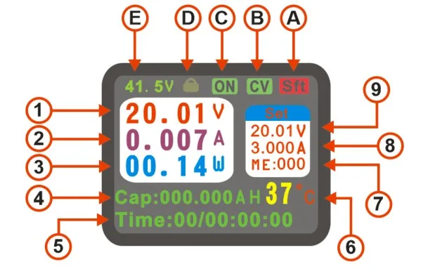
1 |
Actual output voltage |
8 |
Set current value |
|
2 |
Actual output current value |
9 |
Set voltage value |
|
3 |
Actual output power value |
A |
Shift key logo |
|
4 |
Cumulative value in real time |
B |
Constant voltage and current status indication |
|
5 |
Runtime value |
C |
Power output switch status |
|
6 |
Internal temperature of power supply |
D |
Key lock indicator |
|
7 |
Data save and recall address |
E |
Actual input voltage value |
|
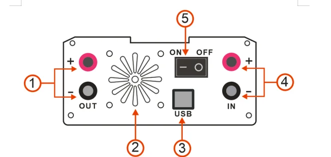
1 |
Output port positive and negative (out) |
|
2 |
Cooling fan outlet |
|
3 |
usb communication port |
|
4 |
Input port positive and negative (in) |
|
5 |
switch |
FIve setting system parameters
|
project |
Features |
range |
|
ovp (output overvoltage protection) |
When the output voltage is higher than the set value, the output will be automatically turned off |
0-60V |
|
ocp (output overcurrent protection) |
When the output current is greater than the set value, the output will be automatically turned off |
0-5A |
|
opp (output over power protection) |
When the output power is higher than the set value, the output will be automatically turned off |
0-300W |
|
otp (over temperature protection) |
When the internal temperature of the power supply is higher than the set value, the output will be automatically turned off. |
0-100℃ |
|
res (output line loss compensation) |
After setting this parameter according to the output wire resistance value, the output voltage can be compensated |
0-9999 milliohms |
|
ato (automatic output after power on) |
Turn on the ato function, and the set voltage value will be automatically output upon power-on |
ON/OFF |
|
sud (sound control) |
Turn sound function on or off |
ON/OFF |
|
lvp (input undervoltage protection value) |
Automatically turn off the output when the input DC voltage value is lower than the set value |
0-60V |
|
ads (address bits) |
Used for multiple online control of different machines using address codes |
0 |
|
Bps (machine communication baud rate) |
57600 by default, cannot be modified |
57600 |
|
Y.S |
Voltage curve coordinate starting voltage value |
0-60V |
|
Y.D |
Voltage curve coordinate termination voltage value |
0-60V |
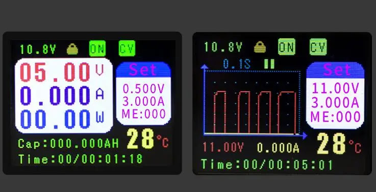
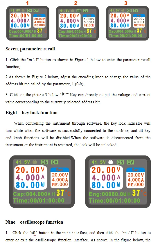
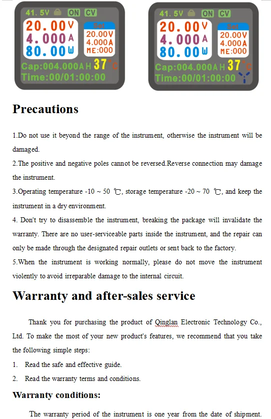
Click the "SFT" button, then click the "Set" button to enter or exit the system parameter setting page. After entering the page, turn the knob to switch the setting parameters (OVP, OCP, LVP, OPP, OTP, RES, ATO, SUD, ADS, YS , YD), click "Set" or press the coding knob to enter the parameter adjustment. The adjustment method is the same as the output voltage and current value adjustment method. The system will automatically exit the parameter setting function within 5 seconds after the parameter is set, and the cursor disappears. After setting the parameters, click the M / L button to enable or disable the protection function. The left picture shows the protection off state, and the right picture shows the protection on state. If the system output state exceeds the set value, the power will automatically disconnect the output, and The reason for disconnection is displayed in the output status item, and if the sound function is started, there will be a short audible alarm.
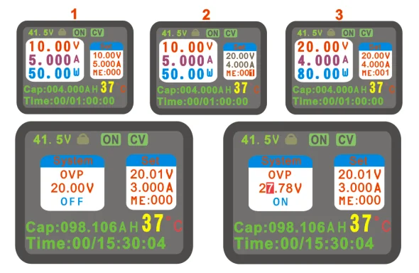
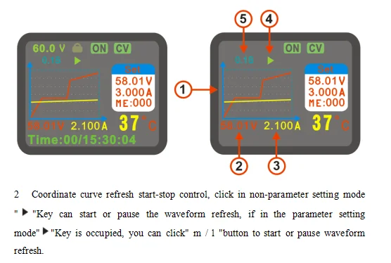
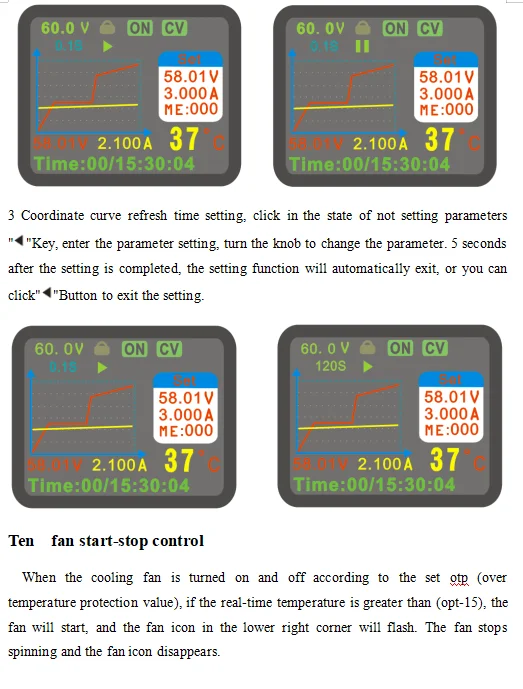
main interface of the oscilloscope function of this instrument is displayed. There are 90 points on the x-coordinate of the curve There are 60 points on the y-axis and the maximum recording time is 3 hours.The refresh time of the curve can be adjusted according to the actual situation.
|
1 |
Coordinate curve (red is voltage curve, yellow is current curve) |
|
2 |
Actual output voltage |
|
3 |
Actual output current value |
|
4 |
Coordinate curve refresh start / stop sign |
|
5 |
Coordinate curve refresh time display (0.1s, 1s, 10s, 30s, 60s, 120s) |
During the warranty period, the company chooses to repair or replace the faulty instrument according to the situation.
The following conditions are not covered by the warranty:
Improper operation or maintenance by the user; use of software or interface provided by the user; modification of the instrument without permission.


Description
Description
一、Instrument introduction
CNC step-down power supply is a fully NC programmable step-down power supply with small size, high power, high efficiency and stable work; it uses a 1.8-inch color LCD display to display comprehensive and clear data; the power supply is controlled by a 32-bit microprocessor It can accurately set and display the voltage and current; it uses buttons and knobs to operate in conjunction with convenient and fast setting parameters, and it can adjust the output voltage and current through the communication between the host computer and the computer and can monitor the output voltage and current in real time, which is very suitable for debugging and maintenance And experimental power.
二、Instrument characteristics
1.Using a 32-bit microprocessor, which can accurately set and display the output voltage and current;
2.Using 1.8-inch color LCD display, it can display the input voltage, output voltage, output current, power, capacity, time, temperature and power supply status in real time;
3.It is convenient and quick to adjust parameters through the combination of buttons and knobs, and the knobs have a button function, which can be adjusted by pressing the knobs, which is very convenient;
4.The output over-voltage protection (Ovp), over-current protection (Ocp), over-power protection (Opp), over-temperature protection (Otp), and input under-voltage protection (Lvp) can be set.When the output exceeds the set value, it can be set. Turn off output;
5.The resistance value of the (Res) power output connection line can be set, which can compensate the voltage drop on the wire;
6.The intelligent temperature-controlled cooling fan dissipates heat to ensure that the power device will not be damaged due to overheating;
7.Can output constant voltage and constant current;
8.With reverse input protection function, can prevent damage to the power supply due to reverse input;
9.With oscilloscope function, it can display the dynamically changing voltage and current curve;
10.Can realize secondary development by communicating with computer or other equipment through serial port;
Third, the technical indicators
|
project |
parameter |
|
Input voltage range |
6V~65V |
|
Output voltage adjustment range |
0 ~ 60v (input needs to be greater than output) |
|
Output current adjustment range |
0~5A |
|
Input protection method |
Reverse connection protection, (Lvp) under voltage protection |
|
Output protection mode |
(Ovp) over voltage, (Ocp) over current, (Opp) over power (Otp) over temperature protection |
|
Output Power |
0~300W |
|
Output voltage setting resolution |
10mV |
|
Output current setting resolution |
1mA |
|
Output ripple |
<100mVpp (input 48V, output 24V, current 5A) |
|
100Hz fluctuation transmission ratio |
< 1/10000 |
|
Typical efficiency |
92% (input 50v, output 30v, current 3a) |
|
Voltage and current display accuracy |
10mV、1mA |
|
Voltage display error |
±1%+10mV |
|
Current display error |
±2%+2mA |
|
Response time |
< 50ms |
|
Store operation |
m0 ~ m9 10 sets of parameter storage |
|
Cooling method |
Aluminum case cooling and cooling fan |
|
Cooling fan startup conditions |
Temperature value is greater than (otp-15) |
|
Operating ambient temperature |
0~60℃ |
|
Ambient storage temperature |
-20~70℃ |
|
Use environment |
Design for indoor use, maximum humidity 80% |
|
Dimensions (length x width x height) |
144×120×55(mm) |
|
1 |
Actual output voltage |
8 |
Set current value |
|
2 |
Actual output current value |
9 |
Set voltage value |
|
3 |
Actual output power value |
A |
Shift key logo |
|
4 |
Cumulative value in real time |
B |
Constant voltage and current status indication |
|
5 |
Runtime value |
C |
Power output switch status |
|
6 |
Internal temperature of power supply |
D |
Key lock indicator |
|
7 |
Data save and recall address |
E |
Actual input voltage value |
|
1 |
Output port positive and negative (out) |
|
2 |
Cooling fan outlet |
|
3 |
usb communication port |
|
4 |
Input port positive and negative (in) |
|
5 |
switch |
FIve setting system parameters
|
project |
Features |
range |
|
ovp (output overvoltage protection) |
When the output voltage is higher than the set value, the output will be automatically turned off |
0-60V |
|
ocp (output overcurrent protection) |
When the output current is greater than the set value, the output will be automatically turned off |
0-5A |
|
opp (output over power protection) |
When the output power is higher than the set value, the output will be automatically turned off |
0-300W |
|
otp (over temperature protection) |
When the internal temperature of the power supply is higher than the set value, the output will be automatically turned off. |
0-100℃ |
|
res (output line loss compensation) |
After setting this parameter according to the output wire resistance value, the output voltage can be compensated |
0-9999 milliohms |
|
ato (automatic output after power on) |
Turn on the ato function, and the set voltage value will be automatically output upon power-on |
ON/OFF |
|
sud (sound control) |
Turn sound function on or off |
ON/OFF |
|
lvp (input undervoltage protection value) |
Automatically turn off the output when the input DC voltage value is lower than the set value |
0-60V |
|
ads (address bits) |
Used for multiple online control of different machines using address codes |
0 |
|
Bps (machine communication baud rate) |
57600 by default, cannot be modified |
57600 |
|
Y.S |
Voltage curve coordinate starting voltage value |
0-60V |
|
Y.D |
Voltage curve coordinate termination voltage value |
0-60V |
Click the "SFT" button, then click the "Set" button to enter or exit the system parameter setting page. After entering the page, turn the knob to switch the setting parameters (OVP, OCP, LVP, OPP, OTP, RES, ATO, SUD, ADS, YS , YD), click "Set" or press the coding knob to enter the parameter adjustment. The adjustment method is the same as the output voltage and current value adjustment method. The system will automatically exit the parameter setting function within 5 seconds after the parameter is set, and the cursor disappears. After setting the parameters, click the M / L button to enable or disable the protection function. The left picture shows the protection off state, and the right picture shows the protection on state. If the system output state exceeds the set value, the power will automatically disconnect the output, and The reason for disconnection is displayed in the output status item, and if the sound function is started, there will be a short audible alarm.
main interface of the oscilloscope function of this instrument is displayed. There are 90 points on the x-coordinate of the curve There are 60 points on the y-axis and the maximum recording time is 3 hours.The refresh time of the curve can be adjusted according to the actual situation.
|
1 |
Coordinate curve (red is voltage curve, yellow is current curve) |
|
2 |
Actual output voltage |
|
3 |
Actual output current value |
|
4 |
Coordinate curve refresh start / stop sign |
|
5 |
Coordinate curve refresh time display (0.1s, 1s, 10s, 30s, 60s, 120s) |
During the warranty period, the company chooses to repair or replace the faulty instrument according to the situation.
The following conditions are not covered by the warranty:
Improper operation or maintenance by the user; use of software or interface provided by the user; modification of the instrument without permission.
Item Specifics
Item Specifics