OCS101 OCXO 10MHz 20M 30M 80M Frequency Reference Crystal Oscillator Clock Calibrator Multiplication Temperature signal module
OCS101 OCXO 10MHz 20M 30M 80M Frequency Reference Crystal Oscillator Clock Calibrator Multiplication Temperature signal module
In stock
-
All orders are dispatched the next 3 business days!
-
We will beat any price. We back all products with a 1 year guarantee.
Order in the next 0 hours 0 minutes to get it by /06/2026
Couldn't load pickup availability
Guaranteed Safe Checkout


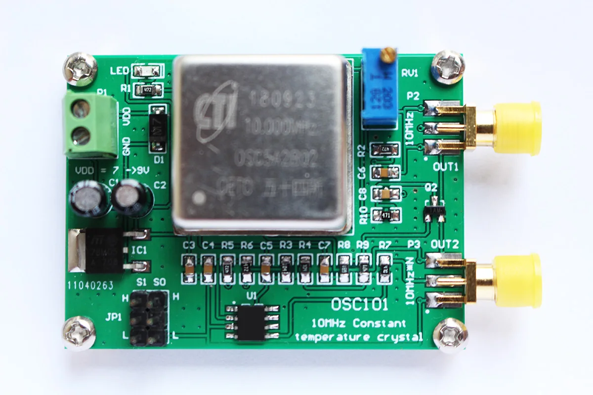
Constant temperature crystal module description
This module outputs the frequency accuracy of the 10MHz signal (+/-200ppb), has two signal outputs, and one is a standard 10MHz signal.
The other is a 10MHz multiplier signal. The multiplier signal has 9 selection frequencies, which are 2X, 3X, 3.125X, 4X, 5X, 5.3125X, 6X, 6.25X, 8X.
The different multipliers are selected by the JP1 jumper pin. Correct the deviation of the 10Mhz output frequency (+/-2.0ppm) with the RV1 potentiometer.
1. P1: Power input interface; (7~9V).
2. P2: 10MHz signal output interface; (10Mhz amplitude: 3Vpp) SMA interface
3. P3: N frequency output interface of 10MHz signal; (N*10Mhz amplitude: 5Vpp) SMA interface
4. RV1: Correct the deviation of the 10Mhz output frequency (+/-2.0ppm)
5.JP1 jumper needle selection
S1=0,S0=0, OUT = 4X
S1=0,S0=M, OUT = 5.3125X
S1=0,S0=1, OUT = 5X
S1=M,S0=0, OUT = 6.25X
S1=M,S0=M, OUT = 2X
S1=M,S0=1, OUT = 3.125X
S1=1,S0=0, OUT = 6X
S1=1,S0=M, OUT = 3X
S1=1,S0=1, OUT = 8X
0 = connect directly to ground(L)
1 = connect directly to VDD(H)
M = leave unconnected(floating)
Length X width X height:56mm*45mm*25mm


Description
Description
Constant temperature crystal module description
This module outputs the frequency accuracy of the 10MHz signal (+/-200ppb), has two signal outputs, and one is a standard 10MHz signal.
The other is a 10MHz multiplier signal. The multiplier signal has 9 selection frequencies, which are 2X, 3X, 3.125X, 4X, 5X, 5.3125X, 6X, 6.25X, 8X.
The different multipliers are selected by the JP1 jumper pin. Correct the deviation of the 10Mhz output frequency (+/-2.0ppm) with the RV1 potentiometer.
1. P1: Power input interface; (7~9V).
2. P2: 10MHz signal output interface; (10Mhz amplitude: 3Vpp) SMA interface
3. P3: N frequency output interface of 10MHz signal; (N*10Mhz amplitude: 5Vpp) SMA interface
4. RV1: Correct the deviation of the 10Mhz output frequency (+/-2.0ppm)
5.JP1 jumper needle selection
S1=0,S0=0, OUT = 4X
S1=0,S0=M, OUT = 5.3125X
S1=0,S0=1, OUT = 5X
S1=M,S0=0, OUT = 6.25X
S1=M,S0=M, OUT = 2X
S1=M,S0=1, OUT = 3.125X
S1=1,S0=0, OUT = 6X
S1=1,S0=M, OUT = 3X
S1=1,S0=1, OUT = 8X
0 = connect directly to ground(L)
1 = connect directly to VDD(H)
M = leave unconnected(floating)
Length X width X height:56mm*45mm*25mm
Item Specifics
Item Specifics