
410-470MHZ 20W/30W UHF RF Radio Power Amplifier AMP 433MHZ For UHF Walkie-talkie Radio With M57704H / M57729H
410-470MHZ 20W/30W UHF RF Radio Power Amplifier AMP 433MHZ For UHF Walkie-talkie Radio With M57704H / M57729H
In stock
-
All orders are dispatched the next 3 business days!
-
We will beat any price. We back all products with a 1 year guarantee.
Order in the next 0 hours 0 minutes to get it by /06/2026
Couldn't load pickup availability
Guaranteed Safe Checkout

(The power amplifier board does not include the power amplifier module and radiator)
The power supply voltage of the power amplifier module will affect the transmission power. Within the working voltage range, the lower the voltage, the smaller the transmission power.
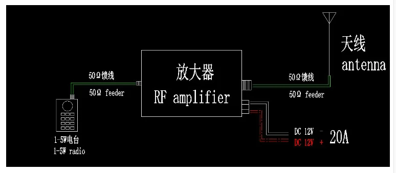
The antenna has a great impact on the communication distance. Please select a matching antenna and install it correctly.
Specifications:
Maximum power of board: 70W
Input power: 1-5W
Transmission frequency: (depending on the model of power amplifier module)
Output power: depending on the installed power amplifier module model
Power supply voltage: 12-13.8V
Standby current: about 10-20mA
Minimum size: 50 * 94mm
Weight: 24g
Installation and commissioning methods:
Before installation, prepare a heat sink with an area larger than the PCB board, and the thickness is recommended to be more than 25MM.
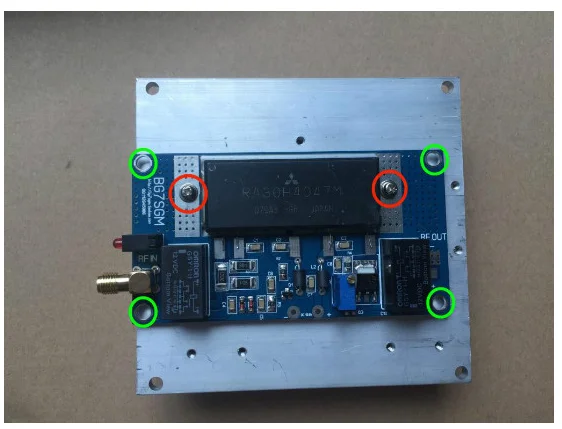
As shown in the above picture, the red mark position is the two screw holes for fixing the power amplifier module and PCB, and it is also the negative pole of the module. When installing, it must be fixed with screws, otherwise the module will not work.
The green mark is used to fix the screw hole of the PCB and is also the GND of the PCB. High frequency circuits are easy to self excitation. To prevent self excitation, it is recommended to fix screws on the radiator, and increase the grounding of the PCB to reduce self excitation.
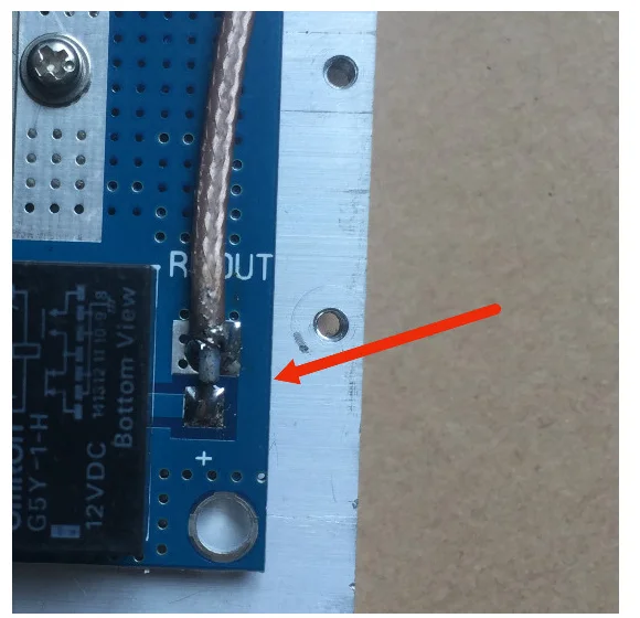
Pay attention to the distance between the bottom element pin and the radiator when screwing the screw. Do not let the element pin touch the radiator to avoid short circuit (as shown in the following picture)
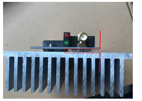
The following picture. Weld the feeder at the power output end (please provide the feeder by yourself)
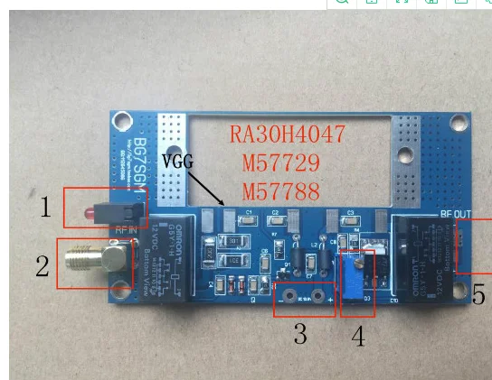
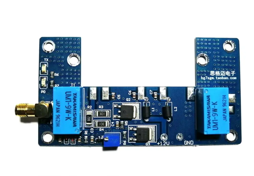
1: Electric indicator (green) emission indicator (red)
2: 1-5W power input (SMA for outer screw and inner hole)
3: DC-12-13.8V power interface
4: Adjust the voltage and power of the second pin (VGG) of the module. The voltage increases clockwise and decreases counterclockwise
5: Refer to the picture for power output interface (upper negative and lower positive)
Commissioning:
Before debugging RA series modules, all pins must be separated from PCB board, and all pins can be welded after voltage adjustment.
The working voltage of the second pin (VGG) from the left of the RA module is 2.3-3.3V (the higher the voltage, the greater the output power). Before debugging, connect the walkie talkie to the PCB board, prepare the multimeter, turn the multimeter to the DC voltage gear, connect the red probe to the second pin (VGG) of the module on the PCB board, connect the black probe to the negative pole, and then press the transmitter button of the walkie talkie, Then adjust the blue potentiometer on the board (which increases clockwise and decreases conversely) to read the voltage value on the multimeter.
The working voltage of M or S series modules is 10-14V, which can be directly installed on the PCB and adjusted to 10-12V。


Description
Description
(The power amplifier board does not include the power amplifier module and radiator)
The power supply voltage of the power amplifier module will affect the transmission power. Within the working voltage range, the lower the voltage, the smaller the transmission power.
The antenna has a great impact on the communication distance. Please select a matching antenna and install it correctly.
Specifications:
Maximum power of board: 70W
Input power: 1-5W
Transmission frequency: (depending on the model of power amplifier module)
Output power: depending on the installed power amplifier module model
Power supply voltage: 12-13.8V
Standby current: about 10-20mA
Minimum size: 50 * 94mm
Weight: 24g
Installation and commissioning methods:
Before installation, prepare a heat sink with an area larger than the PCB board, and the thickness is recommended to be more than 25MM.
As shown in the above picture, the red mark position is the two screw holes for fixing the power amplifier module and PCB, and it is also the negative pole of the module. When installing, it must be fixed with screws, otherwise the module will not work.
The green mark is used to fix the screw hole of the PCB and is also the GND of the PCB. High frequency circuits are easy to self excitation. To prevent self excitation, it is recommended to fix screws on the radiator, and increase the grounding of the PCB to reduce self excitation.
Pay attention to the distance between the bottom element pin and the radiator when screwing the screw. Do not let the element pin touch the radiator to avoid short circuit (as shown in the following picture)
The following picture. Weld the feeder at the power output end (please provide the feeder by yourself)
1: Electric indicator (green) emission indicator (red)
2: 1-5W power input (SMA for outer screw and inner hole)
3: DC-12-13.8V power interface
4: Adjust the voltage and power of the second pin (VGG) of the module. The voltage increases clockwise and decreases counterclockwise
5: Refer to the picture for power output interface (upper negative and lower positive)
Commissioning:
Before debugging RA series modules, all pins must be separated from PCB board, and all pins can be welded after voltage adjustment.
The working voltage of the second pin (VGG) from the left of the RA module is 2.3-3.3V (the higher the voltage, the greater the output power). Before debugging, connect the walkie talkie to the PCB board, prepare the multimeter, turn the multimeter to the DC voltage gear, connect the red probe to the second pin (VGG) of the module on the PCB board, connect the black probe to the negative pole, and then press the transmitter button of the walkie talkie, Then adjust the blue potentiometer on the board (which increases clockwise and decreases conversely) to read the voltage value on the multimeter.
The working voltage of M or S series modules is 10-14V, which can be directly installed on the PCB and adjusted to 10-12V。
Item Specifics
Item Specifics


