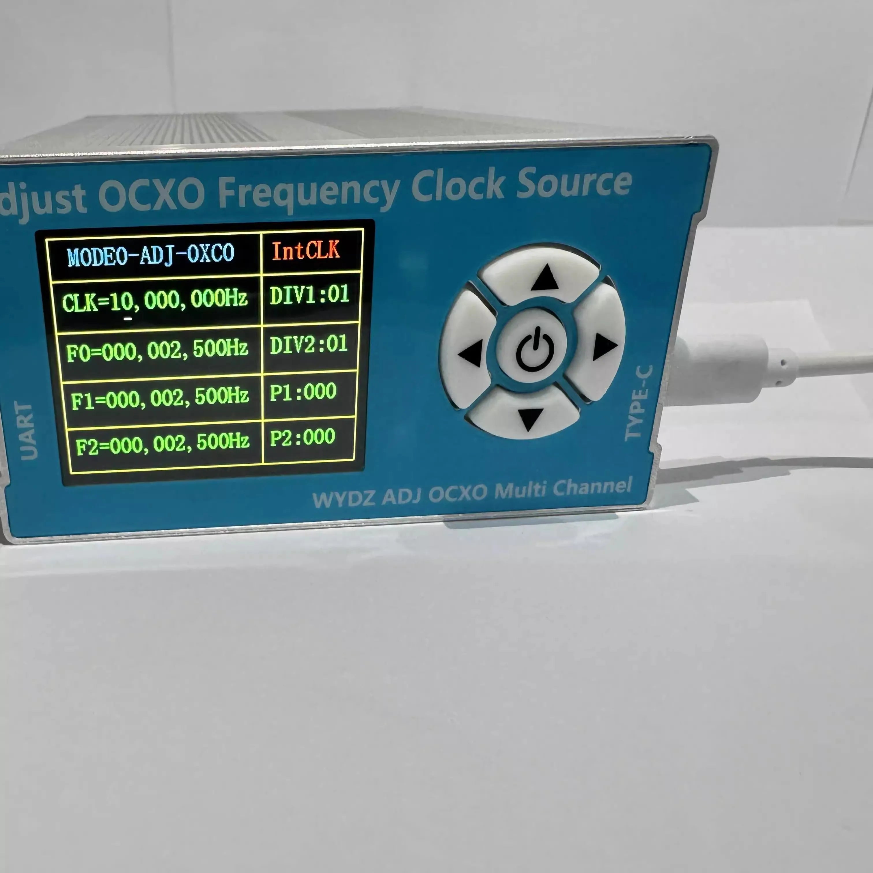
10M 0.1ppm OCXO Adjustable Frequency Standard 2.5K-200M Clock Source Module w/ SMA Female Connectors +LCD + PC software
In stock
-
All orders are dispatched the next 3 business days!
-
We will beat any price. We back all products with a 1 year guarantee.
Order in the next 0 hours 0 minutes to get it by /12/2025
Couldn't load pickup availability
Guaranteed Safe Checkout
Clock Source Parameters:
1. Frequency range: 2500Hz-200MHz
2. Amplitude-peak-to-peak:
MODE0:
* F0: 3.21Vpp
* F1: 3.23Vpp
* F2: 3.21Vpp
MODE1:
* F0: 3.15Vpp
* F1: 3.12Vpp
* F2: 3.12Vpp
3. Power supply requirements: 5V 1A TYPE-C power supply. The power-up is at 800mA. The current will be 400mA after the internal OCXO is stabilized
4. Weight: 400g/0.9lb
5. Input and output interface: SMA female connectors
6. Size: 13cm x 9.6cm x 5cm/5.1" x 3.8" x 2" (LxWxH)
Package Included:
- 1 x Clock Source Module
Packaging Details:
- Weight: 0.65kg
Introduction of Buttons:


MODE0:

CLK stands for clock source frequency. F0 represents the signal frequency of channel 1. DIV1 and DIV2 are division factors. F1=F0/DIV1 and F2=F0/DIV2. P1 is the phase difference between F0 and F1, and P2 is the phase difference between F0 and F2.
As shown in the figure above, F0 = 50 MHz, division factor DIV1 = DIV2 = 10, F1 = F0/DIV1 = 5 MHz, and F2 = F0/DIV2 = 5 MHz.
MODE1:

CLK stands for clock source frequency. F0 represents the signal frequency of channel 1. DIV1 is the division factor. F2=F1/DIV1. P1 is the phase difference between F1 and F2.
As shown in the figure above, F0 = 120 MHz and the division factor DIV1 = 10. F0 is an independent frequency. F2=F1/DIV1=1.01MHz.
PC CLK Source Controller:

Waveform Data Graph:
MODE0 Oscillogram at 2500Hz and 50M:


MODE1 Oscillogram at 2500Hz and 50M:


Clock Frequency Meter to Measure Its Accuracy:


Description
Description
Clock Source Parameters:
1. Frequency range: 2500Hz-200MHz
2. Amplitude-peak-to-peak:
MODE0:
* F0: 3.21Vpp
* F1: 3.23Vpp
* F2: 3.21Vpp
MODE1:
* F0: 3.15Vpp
* F1: 3.12Vpp
* F2: 3.12Vpp
3. Power supply requirements: 5V 1A TYPE-C power supply. The power-up is at 800mA. The current will be 400mA after the internal OCXO is stabilized
4. Weight: 400g/0.9lb
5. Input and output interface: SMA female connectors
6. Size: 13cm x 9.6cm x 5cm/5.1" x 3.8" x 2" (LxWxH)
Package Included:
- 1 x Clock Source Module
Packaging Details:
- Weight: 0.65kg
Introduction of Buttons:


MODE0:

CLK stands for clock source frequency. F0 represents the signal frequency of channel 1. DIV1 and DIV2 are division factors. F1=F0/DIV1 and F2=F0/DIV2. P1 is the phase difference between F0 and F1, and P2 is the phase difference between F0 and F2.
As shown in the figure above, F0 = 50 MHz, division factor DIV1 = DIV2 = 10, F1 = F0/DIV1 = 5 MHz, and F2 = F0/DIV2 = 5 MHz.
MODE1:

CLK stands for clock source frequency. F0 represents the signal frequency of channel 1. DIV1 is the division factor. F2=F1/DIV1. P1 is the phase difference between F1 and F2.
As shown in the figure above, F0 = 120 MHz and the division factor DIV1 = 10. F0 is an independent frequency. F2=F1/DIV1=1.01MHz.
PC CLK Source Controller:

Waveform Data Graph:
MODE0 Oscillogram at 2500Hz and 50M:


MODE1 Oscillogram at 2500Hz and 50M:


Clock Frequency Meter to Measure Its Accuracy:


Item Specifics
Item Specifics
Share
Have a Question?
✲
Precision fit for your specific vehicle model.
Collection slider
Give customers details about the collection or content on the template.